Game of Life on the MEGA65, in BASIC
Conway’s Game of Life is a classic math game that’s also a fun beginner’s programming project. With a grid of cells and a few simple rules, a flourishing biome of digital organisms comes to life. Let’s try building it for the MEGA65 using BASIC!
Articles in this series:
- Game of Life on the MEGA65, in BASIC
- Game of Life on the MEGA65, in assembly language
- Using the MEGA65 Monitor to troubleshoot assembly programs
- Using MEGA65’s Matrix Mode
The rules of Life
An obligatory review of the rules:
- The action takes place on a square grid of cells. Each cell is either alive or dead.
- The game begins with a pattern of alive and dead cells. The goal is to calculate the next pattern (or generation) from a set of evolutionary rules.
- The next generation of each cell is determined by the surrounding eight cells of the current generation:
- If a given cell is alive, it stays alive if surrounded by exactly two or three alive cells.
- If a given cell is dead, it becomes alive if surrounded by exactly three alive cells.
- Otherwise the cell is dead in the next generation.
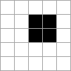
Consider this pattern of three alive cells arranged vertically:

In the next generation, the middle cell will stay alive because it has two alive neighbors, one above and one below. The top and bottom neighbors will not fare as well: with only one alive neighbor each (the middle cell), they will be dead in the next generation. Of the surrounding dead cells, two will spring to life because they have three alive neighbors: the cell to the left of the middle, and the cell to the right of the middle. The second generation looks like this:

What will the third generation look like? By the same reasoning, we can determine that the third generation is identical to the first: the middle cell survives, the outer alive cells die, and the adjacent top and bottom dead cells come back to life. A pattern that repeats like this is called an oscillator. This particular oscillator is known as the “blinker.”
A 2-by-2 square of cells is known as the “block,” an example of a still life pattern: all of the cells stay the same between generations. Each alive cell has three alive neighbors, and no dead cells have enough alive neighbors to come to life.
Mathematicians and enthusiasts have discovered many entertaining patterns that arise from these rules. A grid full of random cells tends to evolve into a set of common stable patterns such as blinkers and blocks. Some simple starting patterns can have long evolutionary lives before they stabilize, such as the infamous R Pentomino.

Getting the game board on screen
Working out patterns on paper or a checkerboard quickly gets tiring. It’s more fun to use a computer!
For our MEGA65 implementation, we will use the 80-column character screen as our grid. Each alive cell will be a filled circle character (Shift-Q), and each dead cell will be an empty space.
In theory, a GoL game board has infinite size. Our MEGA65 does not have infinite memory, so we need to compromise by setting a boundary. We will limit our game board to the size of the text mode screen. We also need a new rule to determine what happens to cells on that boundary. For our purposes, cells outside the boundary are considered permanently dead.
Another fun option would be to have the game board wrap around the sides: a cell on the left edge of the screen has cells on the right edge of the screen as its neighbors, and same top to bottom. This forms a torus surface, and allows larger patterns to spill over the sides without being eaten up by a dead border. We will start with the dead border for our initial version.
A first attempt
Our computer program will walk methodically through every cell of the game board, deciding what the new state will be based on the state of the surrounding cells. It will be important to keep data about the previous generation in memory while calculating the next generation, so we’ll need to think about how this is stored in memory.
As a first attempt in BASIC, let’s imagine two 2-dimentional arrays, one for the current generation and one for the next generation, storing a 1 for alive cells and 0 for dead cells. To calculate the next from the current, we loop over each column and row, add up the neighbor cells from the current board, then set the cell on the next board based on the rules.
Ignoring how we might draw the board to the screen for a moment, here’s some naïve BASIC that might iterate one board to the next:
100 DIM CB(80,25),NB(80,25)
110 FOR R=0 TO 24
120 FOR C=0 TO 79
130 TT=CB(C-1,R-1)+CB(C,R-1)+CB(C+1,R-1)+CB(C-1,R)
140 TT=TT+CB(C+1,R)+CB(C-1,R+1)+CB(C,R+1)+CB(C+1,R+1)
150 IF TT=3 OR CB(C,R)=1 AND TT=2 THEN 170
160 NB(C,R)=0 : GOTO 180
170 NB(C,R)=1
180 NEXT C
190 NEXT R
Not too shabby, but there’s already a problem. When calculating a cell on the edge of the screen, this code attempts to look at a neighbor off the edge, outside the bounds of the array. Looking to the left of column 0, this tries to access column 0-1 = -1, which fails with an ?ILLEGAL QUANTITY ERROR.
We could add some IF statements to avoid looking outside the array. This would turn lines 130 and 140 into a dozen or so lines.
Instead, we’ll make a design decision to simplify: our “dead border” is the outer edge of the array, initialized to 0 by the DIM statements. We will only evolve the region just inside this border. This requires only one small change:
110 FOR R=1 TO 23
120 FOR C=1 TO 78
Now the program can look in all eight directions for every cell without falling off the array.
We haven’t set an initial pattern in CB yet, so let’s set up the blinker on the current board CB:
105 CB(4,3)=1 : CB(4,4)=1 : CB(4,5)=1
Running this code produces the 2nd generation of the blinker in array NB. We can’t see it yet, but it’s there.
Drawing to the screen
We decided to use 80x25 text mode for our display. We could draw all of the cells using character strings and PRINT statements, but there’s a much easier way: we can write directly to screen memory using POKE.
By default, screen memory starts at address $0800 (or 2048 decimal). Characters are stored as screen codes, one byte per character, one row at a time. In 80-column mode, the first 80 bytes are the screen codes of the first row, the next 80 bytes are the second row, and so on. With R as a row number between 0 and 24 and C as a column number betweeen 0 and 79, we can calculate the screen memory position like so:
AA = $0800 + 80*R + C
The screen code for a filled circle character is $51, and the screen code for a space is $20. For example, to draw a filled circle at column 8 row 5:
POKE $0800 + 80*5 + 8, $51
We can update our first attempt to draw NB as it is storing it, like so:
160 NB(C,R)=0 : POKE $0800 + 80*R + C, $20 : GOTO 180
170 NB(C,R)=1 : POKE $0800 + 80*R + C, $51
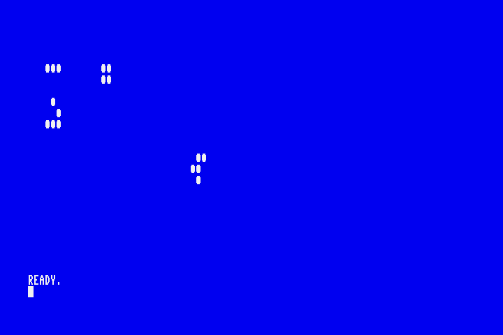
This program prints the board to the screen as it is being evaluated. We can see our cells!
Multiple generations
We have an initial pattern in CB, a way of generating the new pattern in NB, and a way of displaying NB as we’re updating it. How do we get this to calculate and display multiple generations, in a loop?
Given how we’ve written the program so far, the easiest thing to do would be to copy NB to CB, then start over. Let’s try that:
200 FOR C=1 TO 78
210 FOR R=1 TO 23
220 CB(C,R) = NB(C,R)
230 NEXT R
240 NEXT C
250 GOTO 110
This works. It’s not particularly fast, but it gets the job done. We can see our blinker in the corner.
How fast is it? Let’s get MEGA65 to tell us. We’ll store the value of the microsecond timer from the reserved variable TI at the beginning of the update, then display the difference at the end. Let’s count the generations while we’re at it.
10 PRINT "{wht}{clr}"
20 G=0

109 TM=TI

250 PRINT "{home}TIME:";TI-TM;" GEN:";G
260 G=G+1
270 GOTO 109
Running the MEGA65 at 40 MHz, this does one generation per 3.69 seconds. Can we do better?
The MEGA65 can run at slower speeds for backwards compatibility with Commodore software. Unsurprisingly, running this code at 1 MHz takes 40x as long, or two minutes per generation. If we adapted this code to a Commodore 64, adjusting the board size to 38x23 to fit a 40-column screen, it would take about 60 seconds per generation. I think I’ll stick to 40 MHz for now.
Fast variables
CBM BASIC allocates and de-references memory for variables as they are used. MEGA65 includes a speed enhancement: all variables with one letter names are pre-allocated, so they are faster for BASIC to find. What happens if we replace our two-letter variable names with single-letter names?
I replaced CB with C. This does not conflict with the C column counter because CBM BASIC treats variables of different types as separate. NB is N, TT is T, and for good measure TM is M.
The result? 3.56 seconds per generation, a savings of 0.13 seconds per generation. Well it’s something.
Avoiding the copy: array flipping?
After each generation, we copy the entirety of the NB array to CB to do it all again. It seems like it’d be faster if we could just tell the program to use NB as the current board and CB as the next board every other generation.
Let’s try it. Instead of two 2-dimensional arrays, we’ll use one 3-dimensional array. The 3rd dimension is either 0 or 1, one for each of two boards, and we keep track of which of the two boards is the current one.
Our new array is DIM B(2,80,25) (B for “board”). We’ll use J and K to store the board number for the current and next board, respectively. These start as 0 and 1, and need to be flipped after each generation. Then we replace references to C(...) and N(...) with B(J,...) and B(K,...), respectively.
100 DIM B(2,80,25) : J=0 : K=1
105 B(J,4,3)=1 : B(J,4,4)=1 : B(J,4,5)=1

130 T=B(J,C-1,R-1)+B(J,C,R-1)+B(J,C+1,R-1)+B(J,C-1,R)
140 T=T+B(J,C+1,R)+B(J,C-1,R+1)+B(J,C,R+1)+B(J,C+1,R+1)
150 IF T=3 OR B(J,C,R)=1 AND T=2 THEN 170
160 B(K,C,R)=0 : POKE $0800 + 80*R + C, $20 : GOTO 180
170 B(K,C,R)=1 : POKE $0800 + 80*R + C, $51

261 IF J=0 THEN 263
262 J=0:K=1:GOTO 270
263 J=1:K=0
We can now delete the copy routine from lines 200-240.
Surprisingly, this does not speed up our program! Even though we removed an entire board traversal step, we’re up to 3.74 seconds per generation, a loss of 0.18 seconds! What happened?
It turns out we’ve actually given BASIC a lot more work to do in the main calculations. Before, BASIC just had to evaluate the row and column expressions, look up the array base address by fast-variable name, then do a row-column address calculation similar to how we find the screen location. Now, we’re asking BASIC to evaluate a third expression for every access and multiply it in. Even though the new expression is just a variable look-up, it has to parse the variable name and access it every single time, in addition to finding the board base address. The new look-ups add up to more work than our copy routine.
Avoiding the copy: just one board
We use two boards because we need to see the current state of every neighbor as we calculate the new state for a given cell. If we just had one board and updated as we went, the next cell would see the new state of the previous cell. That isn’t how the Game of Life is played.
It turns out we don’t need to keep the entire current board as we build the new one. As we update cells left to right, top to bottom, we only need to remember two rows’ worth, just enough so that as we update the board, we can still access the previous state for the remaining rows. This new algorithm lets us update the board in place, without having to copy anything at the end.
We create two row buffers, one for the previous row and one for the current row. To update, we traverse the board left to right, top to bottom. For each cell in a row:
- Store the current cell value in the current row buffer.
- Use the previous row buffer to access the three neighbors above the current cell, and the current row buffer to access the neighbor to the left. Use the board itself to access the neighbors to the right and below.
- Update the current cell directly on the board.
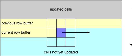
For the next row, we use the previous row’s current-row buffer as the previous-row buffer, and build a new current-row buffer. We can use the array flipping trick we tried earlier for this.
Despite the newness of the algorithm, the new code resembles the old code nicely. B(C,R) is the board, D(J,C) is the previous row buffer, and D(K,C) is the current row buffer. The updates are mostly just changing the way the cell values are accessed, building the current row buffer, and flipping the row buffers once per row.
100 DIM B(80,25) : DIM D(2,80) : J=0 : K=1
105 B(4,3)=1 : B(4,4)=1 : B(4,5)=1

125 D(K,C)=B(C,R)
130 T=D(J,C-1)+D(J,C)+D(J,C+1)+D(K,C-1)
140 T=T+B(C+1,R)+B(C-1,R+1)+B(C,R+1)+B(C+1,R+1)
150 IF T=3 OR B(C,R)=1 AND T=2 THEN 170
160 B(C,R)=0 : POKE $0800 + 80*R + C, $20 : GOTO 180
170 B(C,R)=1 : POKE $0800 + 80*R + C, $51
180 NEXT C
190 IF J=0 THEN 192
191 J=0:K=1:GOTO 200
192 J=1:K=0
200 NEXT R
We’re down to 3.28 seconds per generation, 0.28 seconds better than our previous best. Improvement!
Using the screen as the board
We’re storing the board as an array, then also POKE’ing a version of the same data to screen memory. Could we use the screen memory directly to store the board?
Let’s answer one question with an experiment: what’s faster, accessing a 2-dimensional array or PEEK’ing an equivalent screen memory location?
1000 DIM B(80,25):R=4:C=5
1010 T=TI:FOR I=1 TO 3000:A=B(C,R):NEXT I:PRINT TI-T
1020 T=TI:FOR I=1 TO 3000:A=PEEK($0800+80*R+C):NEXT I:PRINT TI-T
I’m giving array access a fair shot here: to PEEK specific coordinates, we have to do address arithmetic each time, similar to what array access would have to do. Sure enough, the array access test finishes in 0.41 seconds, while the equivalent PEEK test finishes in 0.58 seconds. If I take out the math and just PEEK($0945) 3,000 times, PEEK finishes in 0.33 seconds. So this may not speed anything up.
Using the screen as the board is still a compelling idea, for a usability advantage. Right now, our initial pattern is set in line 105 with a bunch of array assignments. If we use the screen as the board, anything that puts filled circles on the screen can set the initial pattern. We can set up the pattern with PRINT statements, or even let the user draw a pattern with the cursor!
Previously, we stored a 1 for alive and 0 for dead. This had the advantage of making counts easy: we just add up the values. The screen stores screen codes; $51 is alive. We might want to support any other screen code as “dead” so the user doesn’t have to completely clear the screen for the update to work. We’ll use the = comparison operator, and store the result:
R = (PEEK($0800+80*R+C)=$51)
The = comparison operator returns -1 if both operands are equal. This isn’t a 1, but that’s OK! We can just add up -1’s instead of 1’s, and negate our targets.
100 DIM D(2,80) : J=0 : K=1
105 PRINT "{home}{down}{down}{down}   "+CHR$($71)+CHR$($71)+CHR$($71)

121 A=$0800+80*R+C
125 D(K,C)=(PEEK(A)=$51)
130 T=D(J,C-1)+D(J,C)+D(J,C+1)+D(K,C-1)
140 T=T+(PEEK(A+1)=$51)+(PEEK(A+79)=$51)+(PEEK(A+80)=$51)+(PEEK(A+81)=$51)
150 IF T=-3 OR PEEK(A)=$51 AND T=-2 THEN 170
160 POKE A, $20 : GOTO 180
170 POKE A, $51
It looks like we get a speed improvement after all: 3.05 seconds per generation, beating the record by 0.23 seconds. I helped it out a bit by pre-calculating the screen address of the current cell, then used simple offsets to find the neighbors.
As a bonus, we can allow the user to draw any GoL starting pattern they want using just an INPUT statement! We can ignore what INPUT puts in the variable, because we just iterate the pattern that’s left on the screen.
10 INPUT"{wht}{clr}DRAW A PATTERN USING SHIFT+Q THEN PRESS RETURN:";A$
15 PRINT"{home}{48 spaces}"
Be careful with order of operations when using the result of a comparison as a number. A=5+3=8 is not the same as A=5+(3=8).
Other BASIC “optimizations?”
With Commodore 64 BASIC programming, it is often considered a best practice to reduce the number of BASIC tokens in order to speed up the program. BASIC reads the tokens of a line fresh every time it executes the line, so giving it less to read can reduce the time it takes. That’s why you see BASIC programs with nearly all of the spaces removed forming ugly unreadable mashes of symbols, like FORC=1TO78.
I used GOTO logic in a couple of cases that could be made into numeric expressions, which might be considered more idiomatic among BASIC programmers. For example, lines 150-170 determine which of two screen codes ($51 or $20) to POKE based on a conditional expression. This could be replaced with a single expression, albeit an arcane one. Try to figure it out:
POKE A,$20+-49*(T=-3 OR PEEK(A)=$51 AND T=-2)
I used GOTO logic to swap J and K, which some of you may have cringed at. Let’s do that more idiomatically, replacing lines 190-192:
Z=J:J=K:K=Z
The logical structure of this program is simple enough that we could combine multiple statements onto fewer lines. Mashing it into a ball and renumbering the lines, we get this:
10 INPUT"{wht}{clr}DRAW A PATTERN USING SHIFT+Q THEN PRESS RETURN:";a$
20 PRINT"{home}{52 spaces}"
30 DIMD(2,80):J=0:K=1:G=1
40 M=TI:FORR=1TO23:FORC=1TO78:A=$0800+80*R+C:D(K,C)=(PEEK(A)=$51)
50 T=D(J,C-1)+D(J,C)+D(J,C+1)+D(K,C-1)
60 T=T+(PEEK(A+1)=$51)+(PEEK(A+79)=$51)+(PEEK(A+80)=$51)+(PEEK(A+81)=$51)
70 POKEA,$20+-49*(T=-3ORPEEK(A)=$51 ANDT=-2)
80 NEXT:Z=J:J=K:K=Z:NEXT
90 PRINT"{home}TIME:";TI-M;" GEN:";G:G=G+1
100 GOTO40
Did any of this help our program run faster? Nope. None of these changes improved execution time. It’s running at 3.047 seconds per generation. I can imagine these things making a difference on a 1 MHz Commodore 64, but I’m fairly convinced that MEGA65 BASIC programs can stay legible without meaningfully impacting performance. BASIC in 40 MHz is a game changer.
More on Life
The Game of Life was invented by mathematician John Conway, and first appeared in Martin Gardner’s “Mathematical Games,” Scientific American, October 1970. Conway died in April 2020; Scientific American has a remembrance. The Wikipedia page on Conway’s Game of Life has animated examples and discusses the history and significance of the game. GoL kicked off a field of recreational mathematics known as cellular automata, with many alternate games with their own rules.
For all the information you could ever want on Conway’s Game of Life, see Conway’s Game of Life: Mathematics and Construction by Nathaniel Johnston and Dave Greene (2022), a complete textbook with exercises. The PDF is a free download, and you can buy it as a quality hardback book.
GoL is a popular computer programming project and there are many implementations, including some that run at high speeds with very large boards. Golly is open source, cross-platform, and widely respected for running cellular automata experiments on modern computers.
Next steps
I’ve got a good start on an assembly language implementation for comparison with BASIC. This article is already long, so I’ll do the write-up of the assembly version as a separate article. (Remember to add my site to your feed reader!) [Update: The assembly language article is here.]
Both CBM BASIC and Game of Life are well studied and I’m probably missing some known optimizations. If you know any, or have ideas for improving the BASIC version, let me know!
If you don’t want to type this in but still want to play with it, you can download it: